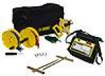
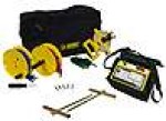
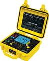
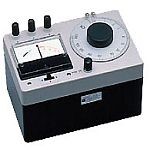
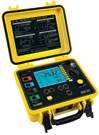
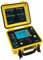
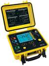
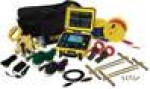
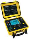
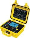
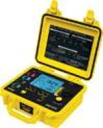
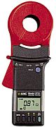
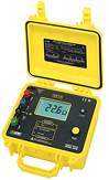
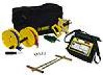
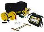
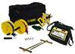
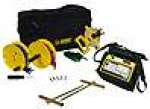
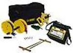
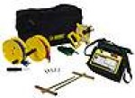
Measures ground resistance (2- and 3-Point) Fall-of-Potential method
Step voltage tests and touch potential measurements
Auto-Ranging: automatically selects the optimum range
Designed to reject high levels of noise interference
Extremely simple to operate: connect - press - read
LED on faceplate informs operator of high input noise, high auxiliary rod resistance and fault connections
Battery powered
Rugged, dustproof and rainproof field case
Can also be used for continuity tests on bonding
Color-coded terminals
Application: Three-Point measurements of resistance to ground of ground rods and grids. Three-point measurements are generally used when the electrode or grid can be easily disconnected, if corrosion is suspected, or in circumstances where ground faults are unlikely to occur. Four-Point tests or soil resistivity measurements. Locating areas of lowest soil resistivity is essential for achieving an economical grounding installation. Touch potential measurements, an alternative to 3-Point tests in evaluating electrical safety. This test is recommended when the ground cannot be disconnected, where ground faults are highly likely to occur, or when the footprint of grounded equipment is comparable to the size of the ground to be tested.
Measures ground resistance (2- and 3-Point) Fall-of-Potential method
Step voltage tests and touch potential measurements
Auto-Ranging: automatically selects the optimum range
Designed to reject high levels of noise interference
Extremely simple to operate: connect - press - read
LED on faceplate informs operator of high input noise, high auxiliary rod resistance and fault connections
AC powered with rechargeable NiMH batteries
Rugged, dustproof and rainproof field case
Can also be used for continuity tests on bonding
Color-coded terminals
Application: Three-Point measurements of resistance to ground of ground rods and grids. Three-point measurements are generally used when the electrode or grid can be easily disconnected, if corrosion is suspected, or in circumstances where ground faults are unlikely to occur. Four-Point tests or soil resistivity measurements. Locating areas of lowest soil resistivity is essential for achieving an economical grounding installation. Touch potential measurements, an alternative to 3-Point tests in evaluating electrical safety. This test is recommended when the ground cannot be disconnected, where ground faults are highly likely to occur, or when the footprint of grounded equipment is comparable to the size of the ground to be tested.
Autoranging: automatically selects the optimum range
Designed to reject high levels of noise and interference
Extremely simple to operate: connect - press - read
LED on faceplate informs operator of high input noise, high auxiliary rod resistance and fault connections
Battery powered
Rugged dustproof and rainproof field case
Color-coded terminals
May be used for continuity tests on bonding
Application: The Ground Resistance Tester Model 3640 is a rugged, easy-to-use instrument ideal for maintenance crews performing numerous tests. The Model 3640 is designed to reject high levels of interference. It can be used under difficult conditions such as high stray currents that normally affect accuracy. The Model 3640 may be used to perform the following tests: Three-Point measurements for measuring resistance to ground of ground rods and grids. Three-Point measurements are generally used when the electrode or grid is easily disconnected, if corrosion is suspected, or where ground faults are unlikely to occur. Two-Point tests for continuity on bonding or on pre-established grounds. This test is commonly performed in urban environments where proper auxiliary electrode placement may be obscured by confined real estate. Measurements are referenced against a good local ground conductor.
Manual or automatic frequency scan from 40 to 513Hz for test accuracy in electrically noisy environments
Earth coupling testing
Selectable test voltage 16 or 32V up to 250mA test current
4-Point soil resistivity measurement with automatic calculation of Rho and user selection of Wenner or Schlumberger test method
2- and 4-Wire DC resistance measurement (Bond testing) with automatic polarity reversal
Auto-off power management
Automatic recognition of all electrode connections and their resistance value
Stores up to 512 complete test results in internal memory
Optically isolated USB communication
Remote set up and operation of all measurements using DataView software supplied
Rechargeable NiMH batteries from wall charger or vehicle power
Rugged dustproof and rainproof field
Includes DataView software
Application: 3-Point measurements of resistance to ground of ground rods and grids. 3-Point measurements are used when electrode or grid can be easily disconnected. 4-Point tests or soil resistivity measurements. Locating areas of lowest soil resistivity is essential for achieving an economical grounding installation. Touch and step potential testing measurements. These tests are recommended when the ground cannot be disconnected, where ground faults are highly likely to occur, or when the "footprint" of grounded equipment (the outline of the part of equipment in contact with earth) is comparable to the size of the ground to be tested. 2- or 4-Wire tests for continuity tests on bonding or on grounding systems. Test is a DC resistive test using 250mA or more and is used to check bonding of all connection points on the ground system. Earth coupling measurement and display. Used to estimate the influence of two earth resistance systems that are not connected to each other.
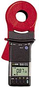
Simple and fast clamp-on operation - no leads, no auxiliary rods or spacing requirements. No need to disconnect neutral service
Direct reading of ground resistance from 0.01ohm to 1200ohm
Direct reading of continuity and ground loop resistance
Direct reading of ground leakage or phase current from 1mA to 30Arms
Jaw design with large 1.25" (32mm) window - accommodates up to 1000MCM cables
Auto-off for power management
Alarm function with adjustable set point and buzzer for quick field checks
Memory function to store 99 field measurements for later retrieval
CE Mark and UL approved
Rugged Lexan head and body construction resists breakage
Alarm settings and stored memory information saved during shutdown
Patented design
Application: Measure electrical ground rod and grid resistance, Use on multi-grounded systems without disconnecting the ground rod under test, Measure resistance and continuity of grounding loops around pads and buildings, Measure leakage current flowing to ground or circulating in ground systems, Conduct field surveys and retrieve and analyze readings at a later time, Use on cell towers and telecommunication sites, Use on pools, spas and other consumer installations.
Manufacture: Yokogawa Product Description: The Yokogawa 3235 Earth Tester is used as a convenient test set for simple, accurate measurements of earth resistance. Without a hand-driven Generator, this instrument consists of battery-operated silicon-transistorized DC-AC inverter, An AC potentiometer measuring dial, and a galvanometer. Just push the push-button switch and move the dial so that the galvanometer shows balanced conditions. Then the resistance is directly read on the dial scale. A Wide range of earth resistance of 0 to 1k Ohms can be measured by a single measuring Dial without range changeover. The earth voltage can also be measured on the galvanometer scale by positioning the selector switch.
Three Input Resistances Ranges - up to 1k Ohms
Accurate, Wide Range Logarithmic Scale
+-5% Accuracy From 2 to 1,000 Ohms
Maximum resolution is 0.1 Ohms
AC potentiometer Bridge, synchronous detector
Portable and shockproof
Specifications:
Measuring Range (Earth Resistance) 0 to 1,000 Ohms (Min. Scale Div. 0.1 Ohms)
Measuring Range (Earth Voltage) 0 to 30 V
Scale (Earth Resistance) 3-dign logarithmic continuous scale on measuring dial
Scale (Earth Voltage) Uniform state on galvanometer
Accuracy (Earth resistance) +-2.5% of 20 Ohms (+-0.5 Ohms or min. one div) in the range of 2 to 20 Ohms +-2.5% of 200 Ohms(+-5% or min. one div.) in the range of 20 to 200 Ohms +-5% of 2 Ohms(+-0,1 Ohms or min. one div.) in the range of 0 to 2 Ohms 5% of 1,000 Ohms(+-50 A or min. one div.) .in the range of 200 to 1,000 Ohms
Accuracy (Earth Voltage) plusmn;5% of full scale value
Measuring Frequency 500 Hz
Ambient Temperature Influence Variation in indication Is within the corresponding one scale division for temperature charge by 20 +- 20 degrees C.
Battery Voltage Influence The accuracy is maintained within the specified limit even if the voltage decreases dawn to approx. 4 V under operating condition.
Earth Voltage Influence Variation in Indication is within the corresponding one scale division for the earth voltages of up to 10V at commercial frequency.
Power Source Four 1.5 V batteries (JIS SUM-1, ANSI D, Mono 1.5 V or equivalent)
Insulation Resistance More than 100M Ohms at 1,000V DC between electrical circuit and case
Dimensions Approx. 122 x 190 x 124 mm (4 7/8 x 7 1/2 x 4 7/8") not including accessories.
Weight Approx. 1.5 kg (3.3 lbs) for Instrument only. Approx. 3.5 kg (7.7 lbs) including all accessories
Accessories1 Accessory storage bag - 1 pcs. (cloth-made knapsack) Carrying case - 1 pcs. (Shoulder bag type) Earth spikes - 2 pcs. (one each for potential and current) Measurement leads (yellow 10 m or 11 yd for potential) 3pcs. Measurement leads (green 5 m or 5.5 yd for earth plate) 3 pcs. Measurement leads (red 20 m or 22 yd for current) 3 pcs.
Optional Accessories B9646CG Auxiliary earthing net
4-Pole (4-Point) Fall-of-Potential measurement for very low resistance measurements with manual or automatic frequency selection and automatic lead compensation
3-Point Fall-of-Potential measurement
3-Point earth coupling measurement
Manual or automatic frequency scan from 40 to 513Hz for test accuracy in electrically noisy environments
Earth coupling testing
Selectable test voltage 16 or 32V up to 250mA test current
4-Point soil resistivity measurement with automatic calculation of Rho and user selection of Wenner or Schlumberger test method
2- and 4-Wire DC resistance measurement (Bond testing) with automatic polarity reversal
Ground Resistance with 2 clamps (no auxiliary rods)
Ground Resistance of Pylons with the GroundFlex Adapter Model 6474 and GroundFlex sensors allow the system to measure leakage current and ground resistance of tower legs without disconnecting the overhead ground conductor.
Includes DataView software for data storage, real-time display, analysis, report generation and system configuration
Auto-off power management
Automatic recognition of all electrode connections and their resistance value
Stores up to 512 complete test results in internal memory
Optically isolated USB communication
Rechargeable NiMH batteries from wall charger or vehicle power
Rugged dustproof and rainproof field
Application: 3-Point measurements of resistance to ground of ground rods and grids. 3-Point measurements are used when electrode or grid can be easily disconnected. 4-Point tests or soil resistivity measurements. Locating areas of lowest soil resistivity is essential for achieving an economical grounding installation. Touch and step potential testing measurements. These tests are recommended when the ground cannot be disconnected, where ground faults are highly likely to occur, or when the ?footprint? of grounded equipment (the outline of the part of equipment in contact with earth) is comparable to the size of the ground to be tested. 2- or 4-Wire tests for continuity tests on bonding or on grounding systems. Test is a DC resistive test using 250mA or more and is used to check bonding of all connection points on the ground system. Earth coupling measurement and display. Used to estimate the influence of two earth resistance systems that are not connected to each other.
4-Pole (4-Point) Fall-of-Potential measurement for very low resistance measurements with manual or automatic frequency selection and automatic lead compensation
3-Point Fall-of-Potential measurement
3-Point earth coupling measurement
Manual or automatic frequency scan from 40 to 513Hz for test accuracy in electrically noisy environments
Earth coupling testing
Selectable test voltage 16 or 32V up to 250mA test current
4-Point soil resistivity measurement with automatic calculation of Rho and user selection of Wenner or Schlumberger test method
2- and 4-Wire DC resistance measurement (Bond testing) with automatic polarity reversal
Ground Resistance with 2 clamps (no auxiliary rods)
Ground Resistance of Pylons with the GroundFlex Adapter Model 6474 and GroundFlex sensors allow the system to measure leakage current and ground resistance of tower legs without disconnecting the overhead ground conductor
Includes DataView software for data storage, real-time display, analysis, report generation and system configuration
Auto-off power management
Automatic recognition of all electrode connections and their resistance value
Stores up to 512 complete test results in internal memory
Optically isolated USB communication
Rechargeable NiMH batteries from wall charger or vehicle power
Rugged dustproof and rainproof field
Application: 3-Point measurements of resistance to ground of ground rods and grids. 3-Point measurements are used when electrode or grid can be easily disconnected. 4-Point tests or soil resistivity measurements. Locating areas of lowest soil resistivity is essential for achieving an economical grounding installation. Touch and step potential testing measurements. These tests are recommended when the ground cannot be disconnected, where ground faults are highly likely to occur, or when the ?footprint? of grounded equipment (the outline of the part of equipment in contact with earth) is comparable to the size of the ground to be tested. 2- or 4-Wire tests for continuity tests on bonding or on grounding systems. Test is a DC resistive test using 250mA or more and is used to check bonding of all connection points on the ground system. Earth coupling measurement and display. Used to estimate the influence of two earth resistance systems that are not connected to each other.
4-Pole (4-Point) Fall-of-Potential measurement for very low resistance measurements with manual or automatic frequency selection and automatic lead compensation
3-Point Fall-of-Potential measurement
3-Point earth coupling measurement
Manual or automatic frequency scan from 40 to 513Hz for test accuracy in electrically noisy environments
Earth coupling testing
Selectable test voltage 16 or 32V up to 250mA test current
4-Point soil resistivity measurement with automatic calculation of Rho and user selection of Wenner or Schlumberger test method
2- and 4-Wire DC resistance measurement (Bond testing) with automatic polarity reversal
Ground Resistance with 2 clamps (no auxiliary rods)
Ground Resistance of Pylons with the GroundFlex Adapter Model 6474 and GroundFlex sensors allow the system to measure leakage current and ground resistance of tower legs without disconnecting the overhead ground conductor
Includes DataView software for data storage, real-time display, analysis, report generation and system configuration
Auto-off power management
Automatic recognition of all electrode connections and their resistance value
Stores up to 512 complete test results in internal memory
Optically isolated USB communication
Rechargeable NiMH batteries from wall charger or vehicle power
Rugged dustproof and rainproof field
Application: 3-Point measurements of resistance to ground of ground rods and grids. 3-Point measurements are used when electrode or grid can be easily disconnected. 4-Point tests or soil resistivity measurements. Locating areas of lowest soil resistivity is essential for achieving an economical grounding installation. Touch and step potential testing measurements. These tests are recommended when the ground cannot be disconnected, where ground faults are highly likely to occur, or when the ?footprint? of grounded equipment (the outline of the part of equipment in contact with earth) is comparable to the size of the ground to be tested. 2- or 4-Wire tests for continuity tests on bonding or on grounding systems. Test is a DC resistive test using 250mA or more and is used to check bonding of all connection points on the ground system. Earth coupling measurement and display. Used to estimate the influence of two earth resistance systems that are not connected to each other."
Test ground resistance using the 2 clamp method (no auxiliary rods needed)
2- and 4-Pole Bond Resistance/Continuity measurement (DC Resistance) with automatic polarity reversal
3-Pole Fall-of-Potential measurement with manual or automatic frequency selection
4-Pole Soil Resistivity measurement with automatic calculation of Rho (r) and user selection of the Wenner or Schlumberger test method
3-Pole Earth Coupling measurement
Manual and Automatic frequency scan from 41 to 513Hz for optimum test accuracy in electrically noisy environments
Selectable test voltage of 16 or 32V up to 250mA of test current
Auto-off power management
Automatic recognition of all electrode connections and their resistance value
Stores up to 512 complete test results in internal memory
Optically isolated USB communication
Remote set up and operation of all measurements using DataView software
Rechargeable NiMH batteries from wall charger or vehicle power
Rugged dustproof and rainproof field case - IP54 rated in closed position
Grounding standards IEC 61557 parts 4 and 5 compliant
Includes DataView software for data storage, real-time display, analysis, report generation and system configuration
Application: 3-Point measurements of resistance to ground of ground rods and grids. 3-Point measurements are generally used when the electrode or grid can be easily disconnected. 4-Point tests or soil resistivity measurements. Locating areas of lowest soil resistivity is essential for achieving an economical grounding installation. Touch and step potential testing measurements. These tests are recommended when the ground cannot be disconnected, where ground faults are highly likely to occur, or when the ?footprint? of grounded equipment (the outline of the part of equipment in contact with the earth) is comparable to the size of the ground to be tested. 2- or 4-Wire tests for continuity tests on bonding or on grounding systems. This test is a DC resistive test using 250mA or more and is used to check bonding of all connection points on the ground system. Earth coupling measurement and display. Used to estimate the influence of two earth resistance systems that are not connected to each other.
Test ground resistance using the 2 clamp method (no auxiliary rods needed)
2- and 4-Pole Bond Resistance/Continuity measurement (DC Resistance) with automatic polarity reversal
3-Pole Fall-of-Potential measurement with manual or automatic frequency selection
4-Pole Soil Resistivity measurement with automatic calculation of Rho (r) and user selection of the Wenner or Schlumberger test method
3-Pole Earth Coupling measurement
Manual and Automatic frequency scan from 41 to 513Hz for optimum test accuracy in electrically noisy environments
Selectable test voltage of 16 or 32V up to 250mA of test current
Auto-off power management
Automatic recognition of all electrode connections and their resistance value
Stores up to 512 complete test results in internal memory
Optically isolated USB communication
Remote set up and operation of all measurements using DataView software
Rechargeable NiMH batteries from wall charger or vehicle power
Rugged dustproof and rainproof field case ? IP54 rated in closed position
Grounding standards IEC 61557 parts 4 and 5 compliant
Includes DataView software for data storage, real-time display, analysis, report generation and system configuration
Application: 3-Point measurements of resistance to ground of ground rods and grids. 3-Point measurements are generally used when the electrode or grid can be easily disconnected. 4-Point tests or soil resistivity measurements. Locating areas of lowest soil resistivity is essential for achieving an economical grounding installation. Touch and step potential testing measurements. These tests are recommended when the ground cannot be disconnected, where ground faults are highly likely to occur, or when the ?footprint? of grounded equipment (the outline of the part of equipment in contact with the earth) is comparable to the size of the ground to be tested. 2- or 4-Wire tests for continuity tests on bonding or on grounding systems. This test is a DC resistive test using 250mA or more and is used to check bonding of all connection points on the ground system. Earth coupling measurement and display. Used to estimate the influence of two earth resistance systems that are not connected to each other.
4-Pole (4-Point) Fall-of-Potential measurement for very low resistance measurements with manual or automatic frequency selection and automatic lead compensation
3-Point Fall-of-Potential measurement
3-Point earth coupling measurement
Manual or automatic frequency scan from 40 to 513Hz for test accuracy in electrically noisy environments
Earth coupling testing
Selectable test voltage 16 or 32V up to 250mA test current
4-Point soil resistivity measurement with automatic calculation of Rho and user selection of Wenner or Schlumberger test method
2- and 4-Wire DC resistance measurement (Bond testing) with automatic polarity reversal
Auto-off power management
Automatic recognition of all electrode connections and their resistance value
Stores up to 512 complete test results in internal memory
Optically isolated USB communication
Remote set up and operation of all measurements using DataView software supplied
Rechargeable NiMH batteries from wall charger or vehicle power
Rugged dustproof and rainproof field
Includes DataView software
Application: 3-Point measurements of resistance to ground of ground rods and grids. 3-Point measurements are used when electrode or grid can be easily disconnected. 4-Point tests or soil resistivity measurements. Locating areas of lowest soil resistivity is essential for achieving an economical grounding installation. Touch and step potential testing measurements. These tests are recommended when the ground cannot be disconnected, where ground faults are highly likely to occur, or when the ?footprint? of grounded equipment (the outline of the part of equipment in contact with earth) is comparable to the size of the ground to be tested. 2- or 4-Wire tests for continuity tests on bonding or on grounding systems. Test is a DC resistive test using 250mA or more and is used to check bonding of all connection points on the ground system. Earth coupling measurement and display. Used to estimate the influence of two earth resistance systems that are not connected to each other.
4-Pole (4-Point) Fall-of-Potential measurement for very low resistance measurements with manual or automatic frequency selection and automatic lead compensation
3-Point Fall-of-Potential measurement
3-Point earth coupling measurement
Manual or automatic frequency scan from 40 to 513Hz for test accuracy in electrically noisy environments
Earth coupling testing
S
Measures earth coupling
Selectable test voltage of 16 or 32V with up to 250mA of test current
4-Point soil resistivity measurement with automatic calculation of Rho (r) and user selection of the Wenner or Schlumberger test method
2- and 4-Wire DC resistance measurement (Bond testing) with automatic polarity reversal
Auto-off power management
Automatic recognition of all electrode connections and their resistance value
Stores up to 512 complete test results in internal memory
Optically isolated USB communication
Remote set up and operation of all measurements using DataView software supplied
Automatic report generation
Rechargeable NiMH batteries from wall charger or vehicle power
Application: 3-Point measurements of resistance to ground of ground rods and grids. 3-Point measurements are used when electrode or grid can be easily disconnected. 4-Point tests or soil resistivity measurements. Locating areas of lowest soil resistivity is essential for achieving an economical grounding installation. Touch and step potential testing measurements. These tests are recommended when the ground cannot be disconnected, where ground faults are highly likely to occur, or when the ?footprint? of grounded equipment (the outline of the part of equipment in contact with earth) is comparable to the size of the ground to be tested. 2- or 4-Wire tests for continuity tests on bonding or on grounding systems. Test is a DC resistive test using 250mA or more and is used to check bonding of all connection points on the ground system. Earth coupling measurement and display. Used to estimate the influence of two earth resistance systems that are not connected to each other.
4-Pole (4-Point) Fall-of-Potential measurement for very low resistance measurements with manual or automatic frequency selection and automatic lead compensation
3-Point Fall-of-Potential measurement
3-Point earth coupling measurement
Manual or automatic frequency scan from 40 to 513Hz for test accuracy in electrically noisy environments
Earth coupling testing
Selectable test voltage 16 or 32V up to 250mA test current
4-Point soil resistivity measurement with automatic calculation of Rho and user selection of Wenner or Schlumberger test method
2- and 4-Wire DC resistance measurement (Bond testing) with automatic polarity reversal
Auto-off power management
Automatic recognition of all electrode connections and their resistance value
Stores up to 512 complete test results in internal memory
Optically isolated USB communication
Remote set up and operation of all measurements using DataView software supplied
Rechargeable NiMH batteries from wall charger or vehicle power
Rugged dustproof and rainproof field
Includes DataView software
Application: 3-Point measurements of resistance to ground of ground rods and grids. 3-Point measurements are used when electrode or grid can be easily disconnected. 4-Point tests or soil resistivity measurements. Locating areas of lowest soil resistivity is essential for achieving an economical grounding installation. Touch and step potential testing measurements. These tests are recommended when the ground cannot be disconnected, where ground faults are highly likely to occur, or when the ?footprint? of grounded equipment (the outline of the part of equipment in contact with earth) is comparable to the size of the ground to be tested. 2- or 4-Wire tests for continuity tests on bonding or on grounding systems. Test is a DC resistive test using 250mA or more and is used to check bonding of all connection points on the ground system. Earth coupling measurement and display. Used to estimate the influence of two earth resistance systems that are not connected to each other.
Simple and fast clamp-on operation - no leads, no auxiliary rods or spacing requirements. No need to disconnect neutral service
Direct reading of ground resistance from 0.01ohm to 1200ohm
Direct reading of continuity and ground loop resistance
Direct reading of ground leakage or phase current from 1mA to 30Arms
Jaw design with large 1.25" (32mm) window - accommodates up to 1000MCM cables
Auto-off for power management
CE Mark and UL approved
Rugged Lexan head and body construction resists breakage
Patented design
Application: Measure electrical ground rod and grid resistance, Use on multi-grounded systems without disconnecting the ground rod under test, Measure resistance and continuity of grounding loops around pads and buildings, Measure leakage current flowing to ground or circulating in ground systems, Conduct field surveys and retrieve and analyze readings at a later time, Use on cell towers and telecommunication sites, Use on pools, spas and other consumer installations.
Autoranging: automatically selects the optimum range
Designed to reject high levels of noise and interference
Extremely simple to operate: connect - press - read
LED on faceplate informs operator of high input noise, high auxiliary rod resistance and fault connections
Battery powered
Rugged dustproof and rainproof field case
Color-coded terminals
May be used for continuity tests on bonding
Application: The Ground Resistance Tester Model 3640 is a rugged, easy-to-use instrument ideal for maintenance crews performing numerous tests. The Model 3640 is designed to reject high levels of interference. It can be used under difficult conditions such as high stray currents that normally affect accuracy. The Model 3640 may be used to perform the following tests: Three-point measurements for measuring resistance to ground of ground rods and grids. Three-point measurements are generally used when the electrode or grid is easily disconnected, if corrosion is suspected, or where ground faults are unlikely to occur. Two-point tests for continuity on bonding or on pre-established grounds. This test is commonly performed in urban environments where proper auxiliary electrode placement may be obscured by confined real estate. Measurements are referenced against a good local ground conductor.
Fall-of-Potential method for 2- and 3-Point ground resistance tests
Direct reading on large analog display 0.5 to 1000ohm and easy 25ohm readings
Large 3.1" (77mm), easy-to-read scale for accurate readings
Built-in battery check
Three color-coded terminals
Large press-to-measure buttons
Portable and compact
Extremely simple to operate: connect - press - read
Designed to reject high levels of noise and interference
Application: The Ground Resistance Tester Model 3620 is the ideal instrument for electrical contractors, power utilities, REAs, telephone and CATV technicians, and inspectors who must check ground to determine compliance with NEC, OSHA and other specifications. Applications include: Measuring earth resistance of the type of single rod or small ground grids often found in remote telecommunication switching sites, Measuring ground electrode resistance of lightning protection equipment, Measuring the earth electrode resistance of equipment in recreational areas, Testing electrode resistance of ground rods and grids at new construction sites, when utility supplied power has not been supplied and Testing earth electrode resistance of grounded towers at cellular phone remote installations.
Measures ground resistance (2- and 3-Point) Fall-of-Potential method
Step voltage tests and touch potential measurements
Auto-Ranging: automatically selects the optimum range
Designed to reject high levels of noise interference
Extremely simple to operate: connect - press - read
LED on faceplate informs operator of high input noise, high auxiliary rod resistance and fault connections
AC powered with rechargeable NiMH batteries
Rugged, dustproof and rainproof field case
Can also be used for continuity tests on bonding
Color-coded terminals
Application: Three-Point measurements of resistance to ground of ground rods and grids. Three-Point measurements are generally used when the electrode or grid can be easily disconnected, if corrosion is suspected, or in circumstances where ground faults are unlikely to occur. Four-Point tests or soil resistivity measurements. Locating areas of lowest soil resistivity is essential for achieving an economical grounding installation. Touch potential measurements, an alternative to 3-Point tests in evaluating electrical safety. This test is recommended when the ground cannot be disconnected, where ground faults are highly likely to occur, or when the "footprint" of grounded equipment is comparable to the size of the ground to be tested. "
Measures ground resistance (2- and 3-Point) Fall-of-Potential method
Step voltage tests and touch potential measurements
Auto-Ranging: automatically selects the optimum range
Designed to reject high levels of noise interference
Extremely simple to operate: connect - press - read
LED on faceplate informs operator of high input noise, high auxiliary rod resistance and fault connections
Battery powered
Rugged, dustproof and rainproof field case
Can also be used for continuity tests on bonding
Color-coded terminals
Application: Three-Point measurements of resistance to ground of ground rods and grids. Three-Point measurements are generally used when the electrode or grid can be easily disconnected, if corrosion is suspected, or in circumstances where ground faults are unlikely to occur. Four-Point tests or soil resistivity measurements. Locating areas of lowest soil resistivity is essential for achieving an economical grounding installation. Touch potential measurements, an alternative to 3-Point tests in evaluating electrical safety. This test is recommended when the ground cannot be disconnected, where ground faults are highly likely to occur, or when the "footprint" of grounded equipment is comparable to the size of the ground to be tested.
Measures ground resistance (2- and 3-Point) Fall-of-Potential method
Step voltage tests and touch potential measurements
Auto-Ranging: automatically selects the optimum range
Designed to reject high levels of noise interference
Extremely simple to operate: connect - press - read
LED on faceplate informs operator of high input noise, high auxiliary rod resistance and fault connections
Battery powered
Rugged, dustproof and rainproof field case
Can also be used for continuity tests on bonding
Color-coded terminals
Application: Three-Point measurements of resistance to ground of ground rods and grids. Three-point measurements are generally used when the electrode or grid can be easily disconnected, if corrosion is suspected, or in circumstances where ground faults are unlikely to occur. Four-Point tests or soil resistivity measurements. Locating areas of lowest soil resistivity is essential for achieving an economical grounding installation. Touch potential measurements, an alternative to 3-Point tests in evaluating electrical safety. This test is recommended when the ground cannot be disconnected, where ground faults are highly likely to occur, or when the footprint of grounded equipment is comparable to the size of the ground to be tested.
Fall-of-Potential method for 2- and 3-Point ground resistance tests
Direct reading on large analog display 0.5 to 1000ohm and easy 25ohm readings
Large 3.1" (77mm), easy-to-read scale for accurate readings
Built-in battery check
Three color-coded terminals
Large press-to-measure buttons
Portable and compact
Extremely simple to operate: connect - press - read
Designed to reject high levels of noise and interference
Double Insulation
CE Mark
Application: The Ground Resistance Tester Model 3620 is the ideal instrument for electrical contractors, power utilities, REAs, telephone and CATV technicians, and inspectors who must check ground to determine compliance with NEC, OSHA and other specifications. Applications include: Measuring earth resistance of the type of single rod or small ground grids often found in remote telecommunication switching sites, Measuring ground electrode resistance of lightning protection equipment, Measuring the earth electrode resistance of equipment in recreational areas, Testing electrode resistance of ground rods and grids at new construction sites, when utility supplied power has not been supplied, and Testing earth electrode resistance of grounded towers at cellular phone remote installations.
Measures ground resistance (2- and 3-Point) Fall-of-Potential method
Step voltage tests and touch potential measurements
Auto-Ranging: automatically selects the optimum range
Designed to reject high levels of noise interference
Extremely simple to operate: connect - press - read
LED on faceplate informs operator of high input noise, high auxiliary rod resistance and fault connections
AC powered with rechargeable NiMH batteries
Rugged, dustproof and rainproof field case
Can also be used for continuity tests on bonding
Color-coded terminals
Application: Three-Point measurements of resistance to ground of ground rods and grids. Three-point measurements are generally used when the electrode or grid can be easily disconnected, if corrosion is suspected, or in circumstances where ground faults are unlikely to occur. Four-Point tests or soil resistivity measurements. Locating areas of lowest soil resistivity is essential for achieving an economical grounding installation. Touch potential measurements, an alternative to 3-Point tests in evaluating electrical safety. This test is recommended when the ground cannot be disconnected, where ground faults are highly likely to occur, or when the footprint of grounded equipment is comparable to the size of the ground to be tested.
Measures ground resistance (2- and 3-Point) Fall-of-Potential method
Step voltage tests and touch potential measurements
Auto-Ranging: automatically selects the optimum range
Designed to reject high levels of noise interference
Extremely simple to operate: connect - press - read
LED on faceplate informs operator of high input noise, high auxiliary rod resistance and fault connections
Battery powered
Rugged, dustproof and rainproof field case
Can also be used for continuity tests on bonding
Color-coded terminals
Application: Three-Point measurements of resistance to ground of ground rods and grids. Three-point measurements are generally used when the electrode or grid can be easily disconnected, if corrosion is suspected, or in circumstances where ground faults are unlikely to occur. Four-Point tests or soil resistivity measurements. Locating areas of lowest soil resistivity is essential for achieving an economical grounding installation. Touch potential measurements, an alternative to 3-Point tests in evaluating electrical safety. This test is recommended when the ground cannot be disconnected, where ground faults are highly likely to occur, or when the footprint of grounded equipment is comparable to the size of the ground to be tested.
Autoranging: automatically selects the optimum range
Designed to reject high levels of noise and interference
Extremely simple to operate: connect - press - read
LED on faceplate informs operator of high input noise, high auxiliary rod resistance and fault connections
Battery powered
Rugged dustproof and rainproof field case
Color-coded terminals
May be used for continuity tests on bonding
Application: The Ground Resistance Tester Model 3640 is a rugged, easy-to-use instrument ideal for maintenance crews performing numerous tests. The Model 3640 is designed to reject high levels of interference. It can be used under difficult conditions such as high stray currents that normally affect accuracy. The Model 3640 may be used to perform the following tests: Three-Point measurements for measuring resistance to ground of ground rods and grids. Three-Point measurements are generally used when the electrode or grid is easily disconnected, if corrosion is suspected, or where ground faults are unlikely to occur. Two-Point tests for continuity on bonding or on pre-established grounds. This test is commonly performed in urban environments where proper auxiliary electrode placement may be obscured by confined real estate. Measurements are referenced against a good local ground conductor.
Measures ground resistance (2- and 3-Point) Fall-of-Potential method
Step voltage tests and touch potential measurements
Auto-Ranging: automatically selects the optimum range
Designed to reject high levels of noise interference
Extremely simple to operate: connect - press - read
LED on faceplate informs operator of high input noise, high auxiliary rod resistance and fault connections
AC powered with rechargeable NiMH batteries
Rugged, dustproof and rainproof field case
Can also be used for continuity tests on bonding
Color-coded terminals
Application: Three-Point measurements of resistance to ground of ground rods and grids. Three-point measurements are generally used when the electrode or grid can be easily disconnected, if corrosion is suspected, or in circumstances where ground faults are unlikely to occur. Four-Point tests or soil resistivity measurements. Locating areas of lowest soil resistivity is essential for achieving an economical grounding installation. Touch potential measurements, an alternative to 3-Point tests in evaluating electrical safety. This test is recommended when the ground cannot be disconnected, where ground faults are highly likely to occur, or when the footprint of grounded equipment is comparable to the size of the ground to be tested.